Installing an ezUHF receiver, fighting noise
So, I moved to UHF because of the bad range using FrSky Taranis combined with 1,3Ghz video.
The best chance of getting good range with UHF is achieved by a selecting the right components, and determining the right placement.
A lot of components used in RC spit out noise on all type of bands. These components are known to emit noise on the 433mhz band:
- Video transmitters (the cheaper the worse).
- UBECs / BECs
- Gopro camera’s
- xxxTVL camera’s (FPV Cams)
- Flightcontrollers (some users report noise from the Naza).
In a new build, you should try to place these components as far away from the UHF receiver as possible. This will reduce the noise picked up by the receiver over the air, however, noise is also emitted over the wires. (Air) noise can also be picked up by wires.
In my case, the F550 is already build, and I didn’t build it with UHF in mind. I increased separation of the components by using 3D printed mounts, and extending the payload arms of the AeroXcraft landing gear (also solving the issue of propellers in the video image). I could improve the component layout a bit by moving the 12v and 5v BEC more forward on the baseplate as well, but for now, let’s just see how far it goes without replacing or moving components.
ImmersionRC ezUHF receivers are able to do a spectrum analysis scan. This is a great tool to check interference, an absolute must when determening the right placement of components and troubleshooting range issues.
So, when you are happy with the placement of all your components, it’s time to find out who is making noise!
The EzUHF interference wizard, build in the immersionRC tools, provide a couple of steps to map the influence of compontents on the noise floor (noise floor is the sum of all unwanted signals).
The steps assume you install UHF on a plane, with servo’s. Because in this case, i’m installing UHF on a multirotor, I did the wizard with the following steps:
Make sure you PC is as far away as possible. I used 3 meter USB cable. I also tested in my living room with all other equipment off, just to be sure, and get the noise from the environment as low as possible.
Step 1: Baseline – Same as a plane offcourse, everything off, only the RX connected using the USB cable.
Step 2: Basic components on – because there are no servo’s on (most) multirotors, I use this step to test the influence of the flightcontroller. In my case I also turn on the UBECs, Minimosd and 3-channel cam switcher because I have to solder them of the power distri board to test without them. When this step increases the noise floor, I should narrow this step down.
Step 3: Step 2+ FPV Cam on
Step 4: Step 3+ Video transmitter on
Step 5: Step 4 + SJ4000 cam while recording – full flight config.
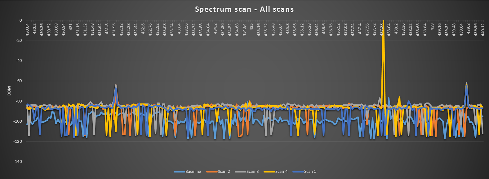
As you can see, most noise comes into play on step 2. This is where I should narrow down my search of the noise source. I suspect the 12V UBEC of most of this noise, because of this post.
I my case, narrowing down the source using the spectrum analyzer means opening up the F550, solder of the 12V and 5V UBEC, and test them one by one. Same goes for the minimOSD. However, I do think a noise floor of ~87dBm is not that bad on a crowded multirotor. I might be able to achieve more than enough range for this setup. Let’s be honest, I moved to UHF because of the poor range the FrSky Taranis gives me in combination with 1,3Ghz video. UHF is meant to achieve tens of kilometers of range, far beyond the range of a heavy F550 on limited battery time.
ImmersionRC ezUHF receivers are able to analyze the UHF band of the spectrum, and plotting the output in a nice graph. The output is also available in a comma separated file (CSV), so you can easily make your own graphs.
I created a little excel graph using the csv file from the interference wizard. You can download it here. Just paste in your results, edit the names of the steps if desired, and there is you nice fancy graph.
Now, I just need to wait for my ezUHF JR module, and set it up.
Thanks for reading!


Leave a Reply