Upgrading the 3D printer to bowden
The Prusa P3Steel is printing fine for a while now, so my hands started itching again….
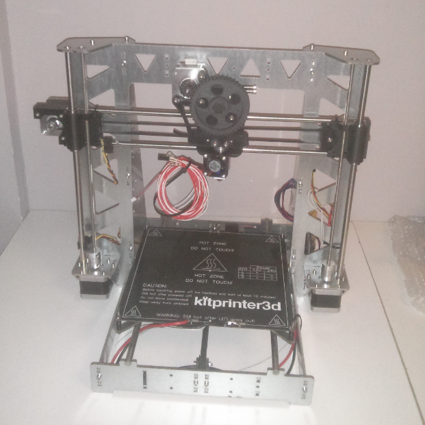
The standard Prusa i3 kit has a so called wades extruder (a geared extruder), this means the extruder (the part that feeds the filament to the hotend (printing nozzle)) is mounted on the moving part of the printing, the X axis.
Keeping the moving part as lightweight as possible would reduce vibrations (which can be seen in the result of the print) and makes is possible to increase the speed of the printer. A bowden setup is the solution to that, in a bowden setup the extruder is placed elsewhere on the (or near) the printer, and the filament is fed to the hotend trough a flexible tube.
There is a large 3D printing community sharing all kind of upgrades with the rest of the world, upgrades can be easily downloaded and printed yourself.
During the research process I stumbled up on a design from ‘airtripper‘, the design looked nice, so I downloaded the files, and printed them out using ABS. I also found an improved X-carriage design using 4 bearings instead of the standard 3 bearings, this should also improve the printers stability a bit.
The parts needed to assemble the extruder can be found on ebay, assembly is just as easy as 1-2-3.
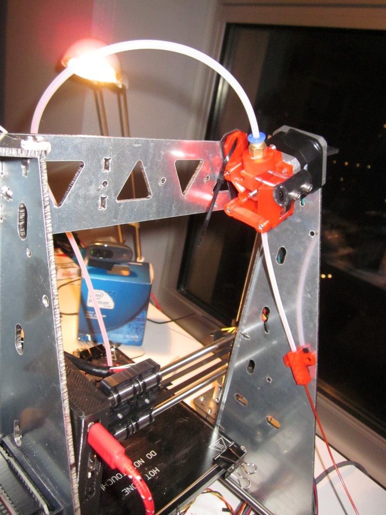
The concept of the extruder is simple: The filament is fed in on the right. Pushed between the MK7 gear (lower part) and ball bearing (upper part) and driven in the telfon tube, to begin its journey to the hotend.
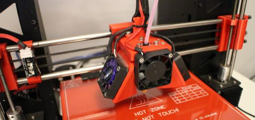
Because i’m going to remove the geared extruder and motor from the X-axis, I also need a new mount to hold the E3D V6 hotend. I decided to use a mount ready to hold 2 E3D V6 hotends, this way I don’t have do disassemble the setup again when I decided I want to a second hotend to the printer. A dual extruder setup is usefull for printing objects in 2 colors or 2 different types of material, for example ABS and PVA (that dissolves in water) as support material to support overhanging parts of a print.
Here is a picture of the dual E3D V6 mount + Proximity sensor mount assembled on the improved X-carriage.
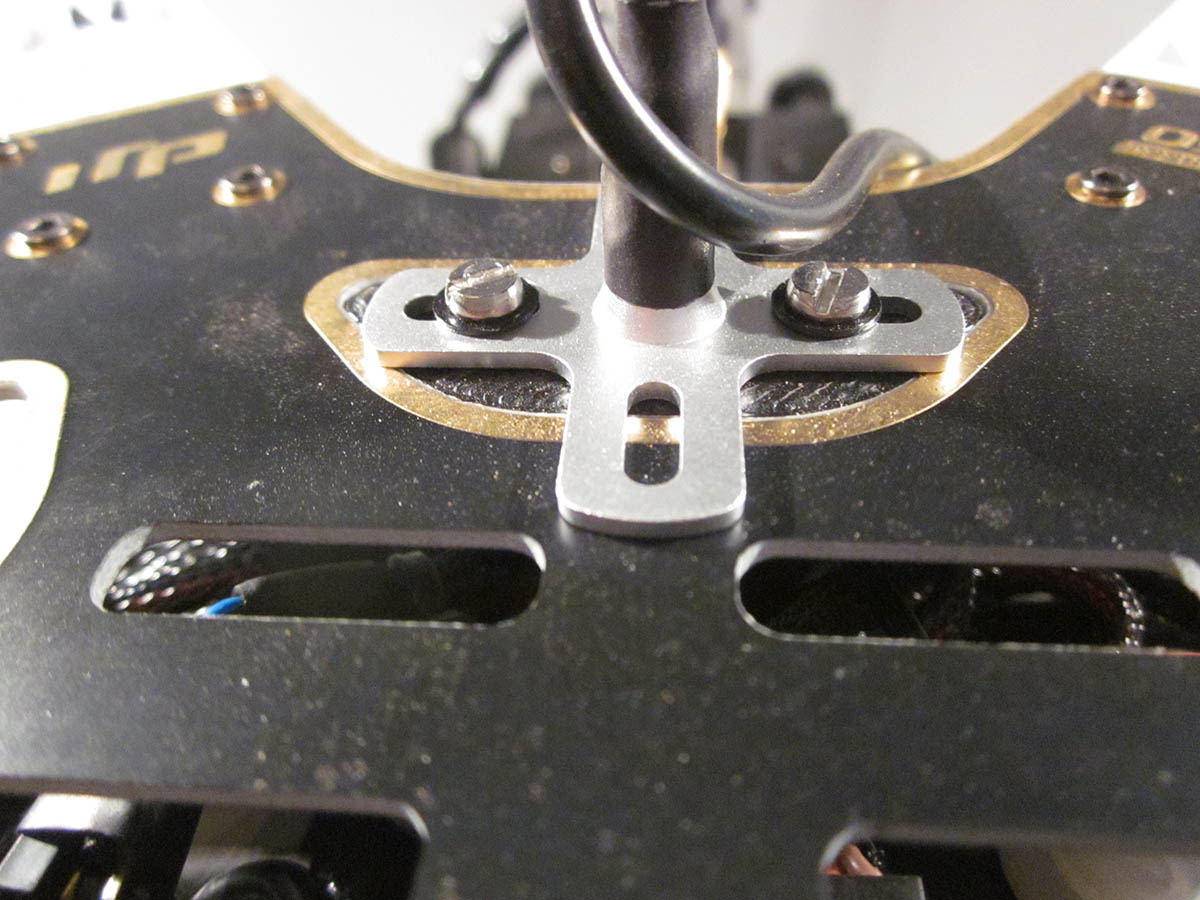
The dual extruder files can be found here. The files include an option to mount a servo for a feature called auto bed leveling. I created a little mount to use this dual extruder mount together with a inductive proximity sensor. More on this later…
The configuration has to be modified. With the old geared extruder, the extruder motor has to make more turns to feed the filament to the hotend, the small gear coupled to a larger gear mounted to the hobbed bolt give the extruder more torque and more precision.
The bowden extruder doesn’t work with gears, but has a MK7 gear mounted directly on the stepper motor. Because the stepper motor has to make more turn to extrude the same amount of filament, we have to modify this in the configuration file of the controller (Arduino + RAMPS 1.4).
The formula for this is:
Current E-steps in config * extruded length in mm / measured distance = New E-steps value
My current config is:
#define DEFAULT_AXIS_STEPS_PER_UNIT {160,160,8000,1550}
When I extrude 100mm with this configuration, the measured distance is 83.43mm
So: 15500 / 83.43 = 185.8 steps per mm
The new config would be:
#define DEFAULT_AXIS_STEPS_PER_UNIT {160,160,8000,185.8}
After uploading this, extrude 100mm filament again, and check of the measured distance now equals the desired distance.
In my case, the 100mm extrusion meassured 100.72mm, so: 18580 / 100.72 = 184.47
My final config now is:
#define DEFAULT_AXIS_STEPS_PER_UNIT {160,160,8000,184.47}
Now, we should be ready to mount the X-carriage, Dual E3D V6 mount and place the hotend. Connect the tube to the hotend and extruder, and start pushing in the filament 🙂




Leave a Reply